
The Tweeters
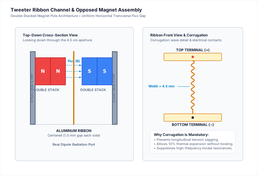
The tweeter magnets are held in the narrow aperture (4.5 cm × 95 cm) by their own magnetic attraction to long steel strips lining the inner sides of the cutout.
The magnetic poles face each other across the gap:
- North pole on one side.
- South pole on the opposite side.
- This generates a strong, uniform transverse horizontal magnetic field across the entire ribbon channel.
Acoustic Phase Alignment: The row of magnets on the side of the tweeter closest to the woofer section must match the polarity of the adjacent woofer row. This ensures both drivers move forward together in acoustic phase when receiving positive voltage.
Magnet Stacking & Clearance
In my build, as in the original Danish project, two magnets are stacked on top of each other along each side to double the field strength (B) in the gap.
The clearance should be adjusted so the aluminum ribbon has approx. 1.0 mm to 1.5 mm clearance from the magnet faces on each side.
Corrugation & Electrical Connections
The pure aluminum ribbon must be corrugated along its length:
- Prevents the ribbon from sagging under its own weight or stretching over time.
- Allows thermal expansion when playing at high volume without bowing into the magnets.
- Distributes mechanical compliance evenly along the strip.
The top and bottom ends are clamped between brass or copper contact blocks with solder lugs leading directly to the crossover high-pass filter.
Original Prototype Sketches
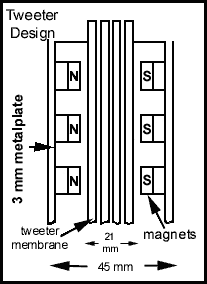 Figure 1: Magnet pole orientation
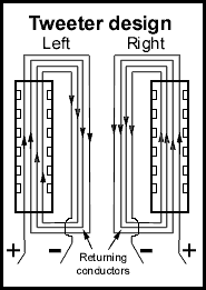 Figure 2: Conductor wiring detail