
The Magnets
This, I feel, is the hardest part of the project (ON YOUR POCKET :-)), investing a large amount of money on a bunch of ceramic or neodymium rectangles for a project you still aren’t completely sure will work…
On top of it all, the original project gives you very little help with respect to the real-life specifications they need to have. I had the “luck” that a Physics Instrumentalist friend of mine casually had 500 magnets of more or less the specs I needed lying around unused after having calibrated some special astronomical CCD camera and was willing to give them to me for free…!
That they were a bit weak in magnetic force was no problem for me. I just planned to put the membrane closer to the magnets: 2 mm instead of the project’s original 5 mm distance.
I had two different types of magnets:
- Tweeter Section: Plastic/flexible magnet type (like the ones used on refrigerators), 5.0 × 1.2 × 0.6 cm. Of those I used 38 per loudspeaker (76 in total).
- Woofer Section: Ceramic bar type, 2.5 × 1.9 × 0.4 cm, of a much lower magnetic strength than the others. Approx. 150 magnets per speaker.
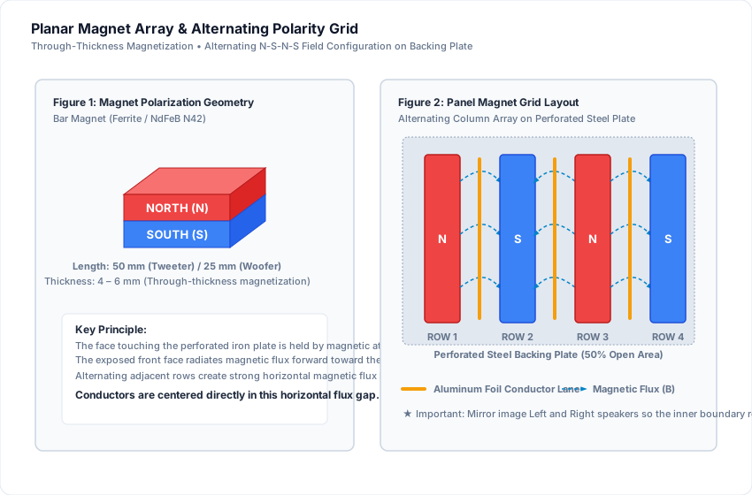
I recommend you find long and thin rectangular magnets that follow the diagram specs with respect to the through-thickness plane of magnetization (Figure 1 above).
Magnet Polarity Grid Layout
Notice the fact that the first row on one plate is the contrary of the other plate—this relates to the tweeter magnets too so that the stereo channels operate in identical acoustical phase.
Original Prototype Sketches
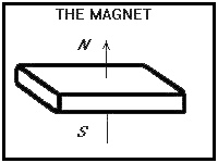 Figure 1: Original single magnet sketch
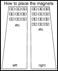 Figure 2: Original magnet grid sketch