
CHAPTER 11 OF 18
The Woofer - The Membrane Conductor Design
M. A. Gallardo
Published 2015-03-11
Verified DIY Build Log
This is the fun part and also the part that requires the most patience and dexterous hands, but using the recommendations in this La Folia project, great results can be easily attained.
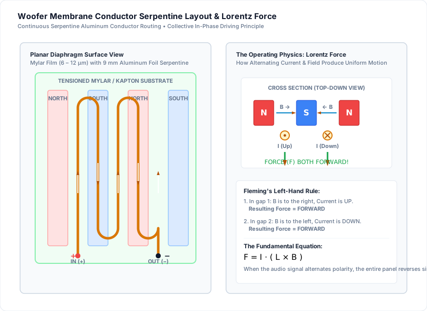
The woofer conductor design must fulfill the general layout as shown in the diagram above.
This also shows you how and why the speaker actually works:
- Notice how the conductors between each alternating magnet polarity have the current flowing in alternating directions (down one gap, up the next).
- Because the magnetic field (B) also alternates direction across adjacent gaps, applying Fleming’s Left-Hand Rule (the three-finger rule) reveals that the electromagnetic Lorentz force (F = I · L × B) acts in the exact same forward direction across all conductor lanes simultaneously!
- When the audio amplifier alternates signal polarity, the force reverses (180° shifted), driving the entire membrane backward in phase.
Key Conductor Specifications
- Conductor Material: Pure annealed aluminum foil (or lightweight copper).
- Trace Width: Approx. 8 mm – 10 mm (distributes current and heat).
- Foil Thickness: 9 µm – 18 µm.
- Target Resistance: 3.0 Ω – 4.0 Ω DC resistance.
Use the Interactive Trace Resistance Calculator to fine-tune your conductor dimensions before cutting foil.
Original Prototype Sketches
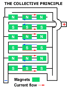 Figure 1: Original three-finger rule diagram
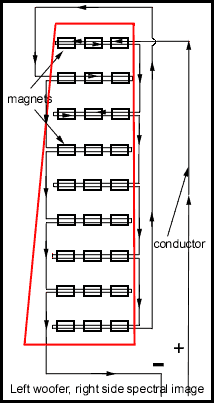 Figure 2: Original serpentine path sketch